Skip to content
English
  • There are no suggestions because the search field is empty.

How to Install and Troubleshoot Current Transformers (CTs) With The Sanctuary System

Please note: The system warranty is voided if any changes to the system are not done by a licensed electrician or one of our certified technicians. If in need of certification, go to certification.lionenergy.com


Useful Files/Links

Sanctuary Installation How to


Overview

Please pay special attention to the installation of the CTs. CT installation errors are the most common problem during installation. An incorrect CT installation will negatively affect the operation of the inverters.


CT Basics

A current transformer (CT) is used to measure the amount of alternating current flowing in a wire. The wire being measured acts as the primary of the transformer, while the CT signal acts as the secondary. The direction of current flow can be determined by comparing the phase of the CT signal with the phase of the voltage on the wire. To properly measure the direction of current, the CT orientation must be correct, or the current’s direction will be interpreted to be the opposite.  

The output of the CT is an AC current at a fraction of the measured current, depending on the CT ratio. Common CT ratios are 1000:1 or 2000:1, meaning the output current is 1/1000th or 1/2000th of the measured current. If the wire the CT is measuring is conducting 100A, and the CT is a 1000:1 ratio, then the CT’s output current will be 0.1A. This output current can be conducted through a resistor to translate current into a voltage, which can be easily measured.  

CTs usually have more features than a simple transformer. Many CTs have voltage clamping circuitry inside to prevent high voltages on the sense wires when they are not connected to a load resistor. A split-core CT can be clamped around a wire without needing to disconnect the wire. 

Note that CTs are directional and have a small engraved arrow on them to show direction. CTs 1 and 2 should be placed on grid input lines 1 and 2, respectively.
 
When using the non-recommended alternate reporting CT placement where other main panel loads such as an air conditioning compressor are not included in the measurements, installers should notify the system owner that the data collected from their system will most likely have large discrepancies from their electrical company's meter.


CT Basics

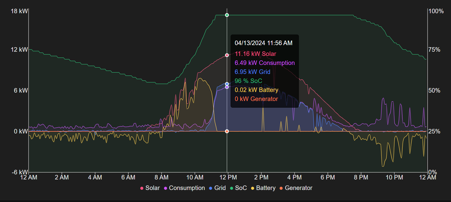
Some home loads, such as air conditioning, may not be connected to the inverter’s load port. These loads are not backed up and will lose power when the grid goes down. To maximize the electric bill savings, the inverter can send power to those loads on demand, without sending more than necessary. If the CT is reading zero current, then the inverter knows it’s sending enough power to the home loads without selling excess to the grid. If the inverter has more solar power than necessary, the excess power can be sold to the grid.  

If the buy vs. sell exchange rates were equal, then there would be no need to store energy in a battery except for powering loads when the grid goes down.  

A typical Utah resident in 2025 may be charged $0.10 per kWh for electricity used but only earns $0.05704 per kWh sold between June and September and only $0.04199 between October and May. Since it costs more to buy electricity than we gain by selling it, we use the battery to store solar energy produced during the day to use at night.


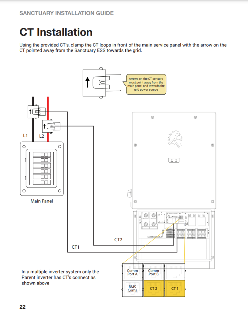
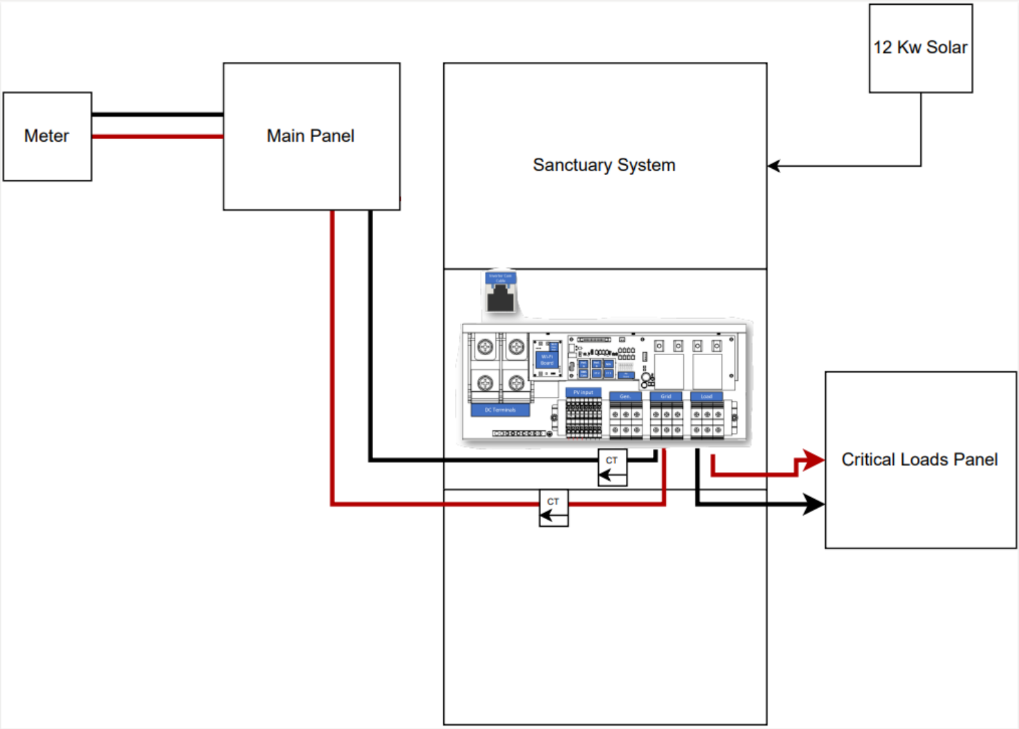
Recommended CT Installation Location
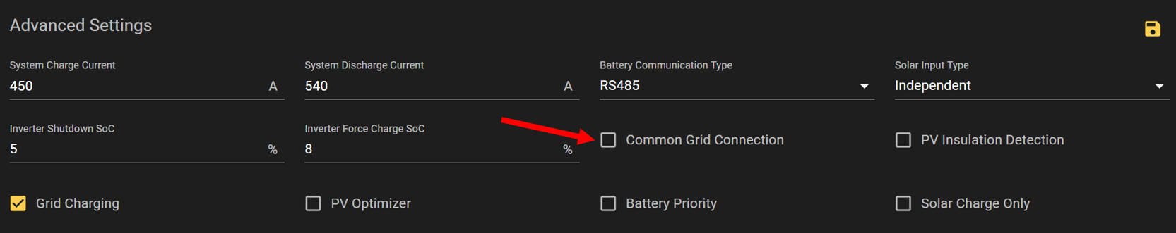
Note that CTs are directional and have a small engraved arrow on them to show direction. CTs 1 and 2 should be placed on grid input lines 1 and 2, respectively. It is recommended that the CTs be placed on the lines between the power meter and the main panel so that the entire home consumption is measured, including the inverter(s). In a whole-home backup situation, if there are no other loads between the inverter’s grid connection and the meter, then the CTs may be placed at the inverter’s grid port. This would be electrically equivalent. 
 
The inverter can send power towards the grid to cover main panel loads that are not on the inverter's essential loads panel. When the setting "CT Limit Current" is set to zero, the inverter can send enough power to cover the loads but not sell power to the grid until the battery is full and there is excess solar beyond what the loads are demanding.
 
When using the non-recommended alternate reporting CT placement at the inverter where other main panel loads such as an air conditioning compressor are not included in the measurements, installers should notify the system owner that the data collected from their system will most likely have large discrepancies from their electrical company's meter.


Common Grid CT

Common Grid CT means that parallel inverters share the data from the parent inverter’s CTs. For parallel inverter systems using the common grid CT configuration, the CTs must be placed above the connection point where all parallel inverters get power from the grid.
 
Data reporting note: When “Common Grid Connection” is enabled, the measured grid current for each CT is divided among the parallel inverters.


CT Connection Location on the Inverter

For Sanctuary 2, revs 1-3, the CT for line 1 is on the bottom right, and line 2 is in the bottom center as shown in this diagram:
 
undefined
 
In this diagram of the COM board, "top" can mean "away from," and "bottom" can mean "towards the inverter" if the pins face down instead of away from the inverter.
 
Page 22 of installation guide
 
undefined


For Multiple Grid Feed Reporting

This is typically done for systems where the homeowner would like to see data from both the home and the Sanctuary, but the installer does not have access to a location where the grid lines for both the home and the system combine. If all the line-1 conductors can’t be grouped into a single CT, or all the line-2 conductors can’t be grouped into a single CT, the signals from multiple CTs can be added using a splitter. The CTs must be of the same type and ratio for this to work properly. 
 
undefined


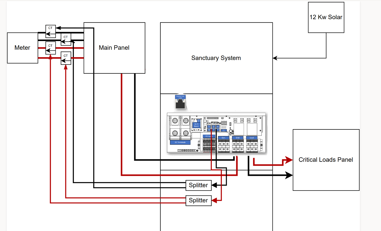
Alternate Configurations

For parallel systems with the setting "Common Grid CT" disabled, each inverter needs the CTs installed at the grid connection point below each inverter. If there are no loads above the grid connections to the inverters, this configuration performs the same as using the Common Grid CT configuration.
 
Data reporting note: When “Common Grid Connection” is disabled, each inverter relies on its own CT measurements for grid current. If one inverter does not have CTs plugged in, it assumes that the grid current is zero and will sell power (usually 8 kW) back to the grid until the battery reaches the time-of-use target SOC.
 

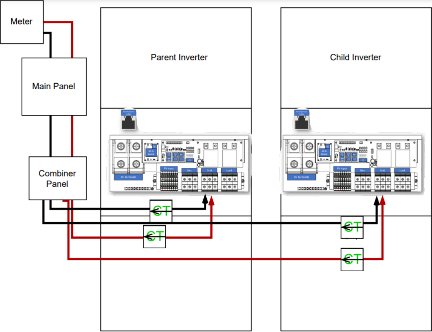
(Alternate Configuration) Parallel Inverter System

undefined
 
If using this connection method on a parallel inverter system, then the installer must go into the advanced settings after commissioning and ensure that the setting “Common Grid Connection” is off as seen here:
 
undefined
 

(Alternate Reporting) Single Inverter

undefined
 

Common Questions (Troubleshooting)

Q: Why does my grid power sell-back at maximum and charge batteries at the same time? The power values don’t add up as if free energy is being generated. At other times, my battery discharges at maximum power while grid usage and load power are way more than I thought possible. I thought I wasn’t even using much electricity at all.
 
A: CTs are on the wrong lines (L1 vs L2) or the arrows are facing the wrong direction.
 
 
Q: Why does my solar sell to the grid and not charge the battery?
 
A: Sell-first mode might be enabled. Go into settings and switch to normal mode to fix it. If this doesn't solve the problem, please contact ESS Support (435) 244-3352.
 
 
Q: Why is my consumption almost mirroring my solar production once my batteries are charged?


undefined
 
A: The wrong CT ratio might have been selected in settings. 
 
or
 
A: The parallel inverter system has might have multiple sets of CTs installed, but has a common grid enabled.
 
or if consumption is always mirroring
 
 
undefined
 
A: The CT’s were placed on the load side instead of the grid
 
 
Q: Why does my consumption disappear once my batteries reach their SoC reserve?
 
 
undefined
 
A: The CT’s are on the wrong lines (L1-L2) either swap line placement or swap RJ-485 ports at the inverter.